HL Series Water Cooled Aftercoolers
Seventy per cent of the water leaves here or not at all
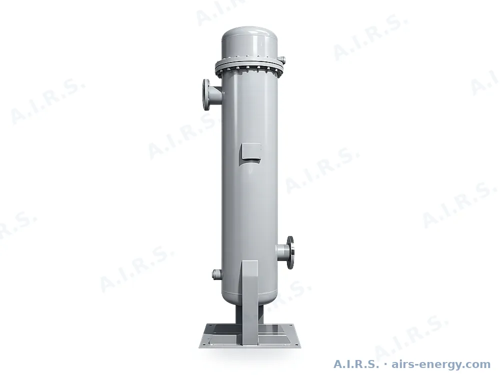
Shell-and-tube water cooled aftercoolers from 3.5 to 300 Nm³/min. Compressed air at up to 100 °C in, 45 °C or below out, with the bulk of the condensate dropped before the air reaches anything with an element in it. Because the approach is to the cooling water, not to ambient, the outlet stays the same on a 45 °C plant floor.
Models: HL-30W to HL-3000W · 24 models · Filtration & air treatment
- ≤ 45 °C Outlet air temperature
- 100 °C Maximum inlet air
- 24 Models in the range
- 300 Nm³/min top capacity
Key specifications
| Medium handled | Compressed air |
|---|---|
| Working pressure | 0.6 – 1.0 MPa |
| Rated inlet air temperature | ≤ 100 °C |
| Outlet air temperature | ≤ 45 °C |
| Cooling water inlet | ≤ 32 °C |
| Cooling water pressure | 0.2 – 0.4 MPa |
| Air flange standard | HG/T 20592-2009 |
| Water and drain threads | GB/T 7307-2001 |
| Blowdown connection | G½" female |
| Construction | Shell and tube, serviceable bundle |
Why this range
- Takes screw compressor discharge directly at up to 100 °C
- Outlet within 10–15 °C of the cooling water, whatever the plant room temperature
- Conventional shell-and-tube with a serviceable, cleanable bundle
- Vertical vessel on a base plate — a fraction of the floor area of an air-cooled unit
- Flanged from HL-200W up; horizontal skid on HL-2500W and HL-3000W
Models and technical data
HL-30W to HL-600W
| Model | Nm³/min | scfm | Water T/h | Air connection | Water conn. | Dimensions mm | kg |
|---|---|---|---|---|---|---|---|
| HL-30W | 3.5 | 134 | 1.2 | G1.5" female thread | G1" | φ168 × 1698 | 60 |
| HL-50W | 6.5 | 250 | 2.1 | G1.5" female thread | G1" | φ219 × 1635 | 86 |
| HL-75W | 10.5 | 403 | 3.5 | G2" female thread | G1.5" | φ219 × 1835 | 95 |
| HL-100W | 13.5 | 518 | 4.4 | G2.5" female thread | G1.5" | φ273 × 1582 | 104 |
| HL-120W | 17 | 653 | 5.8 | G2.5" female thread | G1.5" | φ273 × 1782 | 115 |
| HL-150W | 21.5 | 826 | 7.3 | G3" female thread | G1.5" | φ273 × 1982 | 125 |
| HL-200W | 28 | 1075 | 9.7 | PL80(A)-10,RF | G1.5" | φ325 × 2040 | 205 |
| HL-300W | 37 | 1421 | 12.7 | PL100(A)-10,RF | G1.5" | φ325 × 2245 | 230 |
| HL-400W | 45 | 1728 | 15.4 | PL100(A)-10,RF | G1.5" | φ377 × 2325 | 296 |
| HL-500W | 55 | 2112 | 18.8 | PL125(A)-10,RF | G2" | φ377 × 2340mm | 306 |
| HL-600W | 65 | 2496 | 22.2 | PL125(A)-10,RF | G2" | φ377 × 2515 | 335 |
At 0.6–1.0 MPa, 100 °C inlet air, 45 °C outlet air and 32 °C cooling water.
HL-700W to HL-3000W
| Model | Nm³/min | scfm | Water T/h | Air connection | Water conn. | Dimensions mm | kg |
|---|---|---|---|---|---|---|---|
| HL-700W | 75 | 2880 | 25.6 | PL125(A)-10,RF | G2" | φ480 × 2730 | 500 |
| HL-800W | 85 | 3264 | 29 | PL125(A)-10,RF | G2" | φ480 × 3030 | 537 |
| HL-900W | 95 | 3648 | 32.4 | PL150(A)-10,RF | G2.5" | φ480 × 3230 | 563 |
| HL-1100W | 110 | 4224 | 37.6 | PL150(A)-10,RF | G2.5" | φ512 × 3225 | 615 |
| HL-1200W | 120 | 4609 | 41 | PL150-10,RF | G2.5" | φ562 × 3180 | 660 |
| HL-1300W | 130 | 4993 | 44.4 | PL150-10,RF | G2.5" | φ562 × 3280 | 680 |
| HL-1400W | 140 | 5377 | 47.8 | PL200-16,RF | G3" | φ612 × 3034 | 796 |
| HL-1500W | 150 | 5761 | 51.2 | PL200-16,RF | G3" | φ612 × 3134 | 819 |
| HL-1600W | 160 | 6145 | 54.7 | PL200-16,RF | G3" | φ612 × 3334 | 869 |
| HL-1800W | 180 | 6913 | 63.8 | PL200-16,RF | G3" | φ662 × 3378 | 1050 |
| HL-2000W | 200 | 7681 | 68.4 | PL200-16,RF | G3" | φ662 × 3578 | 1120 |
| HL-2500W | 250 | 9601 | 85.6 | PL250-16,RF | PL100-16,RF | 2300 × 750 × 950 | 1050 |
| HL-3000W | 300 | 11521 | 102.5 | PL250-16,RF | PL100-16,RF | 2800 × 750 × 950 | 1200 |
Allow clearance at one end for bundle withdrawal.
Air cooled against water cooled
| Air cooled | Water cooled HL Series | |
|---|---|---|
| Outlet air temperature | Ambient + 10 to 15 °C | Cooling water + 10 to 15 °C |
| On a 45 °C plant floor | 55 – 60 °C — unusable for adsorption | Unchanged, 40 – 45 °C |
| Heat rejected | Into the compressor house | To the cooling tower |
| Footprint | Larger — needs clear airflow | Compact vertical vessel |
| Services required | Electrical for the fan | Cooling water circuit |
| Seasonal variation | Follows the weather | Follows the tower, far more stable |
Where it is used
- Directly after the compressor
- Ahead of a receiver on a hot system
- In front of an adsorption dryer
- Retrofit where the packaged cooler runs hot